Music and Lights
An Arduino powered entertainment package
Summary
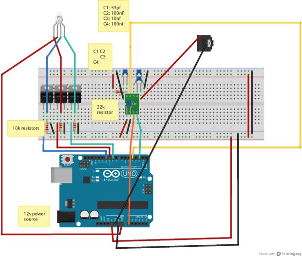
I took an Arduino microcontroller, added a special chip that takes audio signal as input, and then wrote a program to translate those audio signals into a signal output that controlled a series of lights. Here is the link to the instructions.
I don’t remember where I heard about the Arduino, but I know as soon as I started working with it, I was hooked.
I had taken a basic electrical engineering course back in high school. The course didn’t teach much, but it did teach the very basics of building a circuit. What a transistor was, what a resistor was, that “Ohms” weren’t just the humming you would do while meditating. It was fun. It was like building Legos, except if you messed up you had the chance of electrocuting yourself.
But more seriously, it’s a lot like those MindStorm Legos that you could use to control motors and stuff. I really enjoyed that stuff because I liked how I could translate my building of stuff into things that would do some sort of physical action. I felt like Iron Man. – NOTE: This probably warrants a post by itself on how I got into IoT kind of projects. If you want to read a longer more in-depth post about my thoughts, I’ll be writing a post on them soon.
Anyways, long story short, I got really into the Arduino world. I loved playing with the LEDs and wanted to make some light up based on my music. But…how do I get started on this? As I was doing this research, I came across a magical item – the MSGEQ7 chip. The SparkFun web page describes the chip: “The seven band graphic equalizer IC is a CMOS chip that divides the audio spectrum into seven bands. 63Hz, 160Hz, 400Hz, 1kHz, 2.5kHz, 6.25kHz and 16kHz.” So, in basic english, it takes an audio input and separates it into seven different bands. This means we can get some sort of electrical signal out of an audio input. Exactly what I was looking for!
We have all the pieces. The basic flow of the project now is:
- Get audio input to pass through MSGEQ7 chip
- Map the output to some sort of number
- Use this number to represent the intensity of one of the RGB LED colors
But the cool thing is… it works! Some things I want to do in the future: